Why Size Matters
Choosing the wrong bowl feeder size is one of the most common and costly mistakes in automation projects. An undersized bowl cannot maintain the required feed rate; an oversized bowl wastes energy and floor space, and the longer part dwell time increases the risk of part damage.
Step 1: Define Your Required Feed Rate
Start with the machine cycle time. If your assembly machine produces one unit every 4 seconds, you need at least 15 parts per minute (ppm) at the bowl outlet — and ideally 20–25% buffer to handle any bowl-level fluctuations. Write this number down: Required feed rate = (60 / cycle time) × 1.25.
Step 2: Measure Your Part
The three critical part dimensions are: maximum length (L), maximum diameter or width (D), and weight (W). Parts with L:D ratio greater than 5:1 (long thin parts) almost always require a centrifugal feeder or stepped belt feeder rather than a bowl feeder.
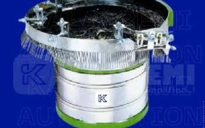
Step 3: Match Bowl Diameter to Part Size
As a rule of thumb, bowl diameter should be at least 8–10 times the maximum part dimension. For a 20 mm screw, a 200 mm bowl is minimum viable; a 250 mm bowl gives more comfortable capacity. For 50 mm caps, a 450–500 mm bowl is appropriate.
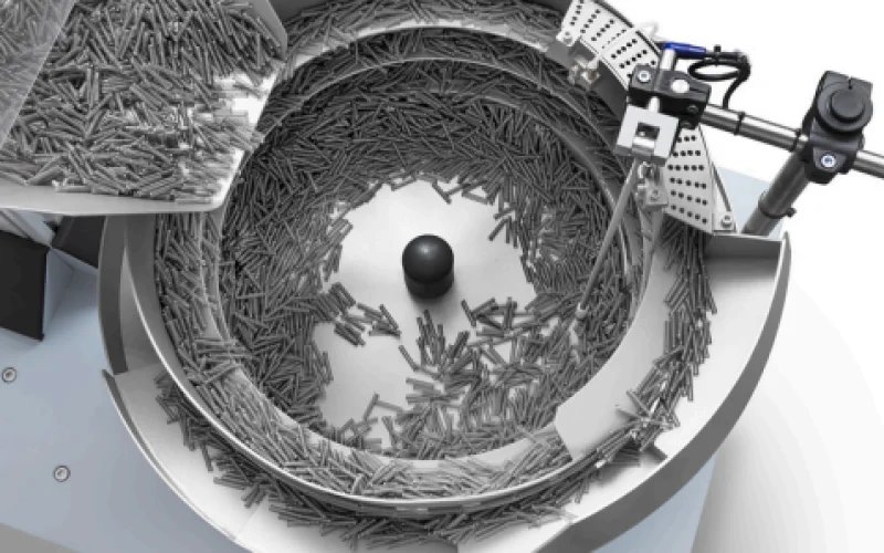
Step 4: Verify Feed Rate vs. Bowl Diameter
Larger bowls can store more parts but don't inherently feed faster — feed rate is determined by track width, vibration amplitude, and tooling geometry. Consult our engineering team with your part drawing and required rate for a definitive recommendation.
Summary Sizing Table
| Part Size | Min Bowl Dia. | Typical Feed Rate |
|---|---|---|
| < 10 mm | 150–200 mm | 100–300 ppm |
| 10–25 mm | 200–300 mm | 60–150 ppm |
| 25–50 mm | 300–450 mm | 30–80 ppm |
| 50–100 mm | 450–600 mm | 15–40 ppm |
| > 100 mm | 600+ mm | 5–20 ppm |