What is Feeder Tooling?
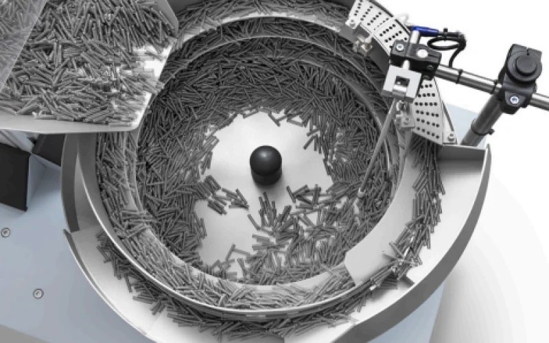
Feeder tooling refers to the physical features — cut-outs, wiper blades, rails, ledges, and air jets — machined or welded into the bowl track that progressively eliminate incorrectly oriented parts until only correctly oriented parts reach the outlet. Tooling design is as much an art as a science, drawing on decades of accumulated knowledge about how specific part geometries behave under vibration.
The Basic Principle
All tooling works on the same principle: correctly oriented parts are stable on the track and pass through or over the tooling feature; incorrectly oriented parts are unstable and are either rejected back into the bowl or flipped into the correct orientation. A typical bowl feeder track has three to six tooling stations in series.
Common Tooling Techniques
1. Wiper Blades
A simple blade positioned above the track rejects parts that are standing upright (correct height exceeds the blade clearance) while allowing flat-lying parts to pass. Simple and effective for cap-type components.
2. Escape Ledges
An undercut in the track lets parts with a flange (like screws or headed pins) ride on the flange with the shank hanging below, while non-flanged parts fall into the undercut and back to the bowl.
3. Back Pressure Rails
A raised rail on the inside of the track pushes parts outward; parts in the correct orientation have their centre of gravity outboard of the rail and continue; parts in the wrong orientation are top-heavy inboard and tip into the bowl.
4. Air Jets
A compressed air nozzle directed at the track ejects parts that are not in the correct orientation. Used when mechanical tooling cannot achieve the required selectivity.
Part Drawing Requirements
To design tooling, Kalapremi engineers need a 2D drawing or 3D model showing all relevant dimensions, tolerances, and weight. Worst-case material tolerances (minimum and maximum dimensions) must be provided to ensure tooling works across the full part variation range.